Outdoor Global Localization
01 May 2020robomagellan robots ros I’ve been making steady progress on the robomagellan robot. In my previous post, I detailed how I calibrated the magnetometer on the robot in preparation for using the robot_localization package to fuse the wheel odometry, IMU, and GPS data. This post discusses the actual use of robot_localization.
Coordinate Frames
Before diving into how the robomagellan robot is localizing, we should explore what the coordinate frames look like. REP 105 specifies the standard conventions for mobile robot coordinate frames in ROS.
For an indoor robot, the coordinate frames are pretty straight-forward. The “center” of the robot is base_link. Your odometry source (typically wheel encoders, often merged with an IMU) is used to generate an odom frame. Then you have a map of the building and a program such as AMCL can use laser scan data to align the robot with the map, publishing a correction in the form of a transformation from odom to map frame. The map frame is arbitrary, but fixed in reference to the map of the building and set at the time the map was built. Goal poses are typically specified in the map frame, since it is consistent over time and over reboots of the robot.
For an outdoor robot, it ends up being more complex. The base_link and odom frames are the same as they were indoors. The map frame origin is less well defined. REP-105 states:
Map coordinate frames can either be referenced globally
or to an application specific position.
With robot_localization, the map frame origin is wherever the robot odometry started. That is a bit different for those of us who mainly use indoor robots where the map frame is consistent from reboot to reboot.
A pair of ROS services are offered which can convert between GPS coordinates and map coordinates. Internally, these services track the location of the map frame in UTM coordinates. The Universal Transverse Mercator (UTM) system splits the world up into a series of coordinate grids. These grids are very large and so you don’t often want to do your calculations in UTM coordinates, hence the local map frame which is located where ever the robot started up. There is an option to publish the utm frame, but it appears rarely used.
Global Localization
“Global” localization is pretty easy with indoor mobile robots based on ROS since it really just consists of finding the robot pose in the map frame. You simply merge an odometry source with your laser scan and a map using AMCL. There are quite a few parameters, but the defaults work pretty well out of the box. Things get a bit more complicated when you go outdoors.
People often improve their odometry source by merging the wheel encoder odometry with an IMU. The robot_localization package offers an Extended Kalman Filter (EKF) that can do this for both indoor and outdoor robots.
While the EKF does not take GPS data directly, the robot_localization package also offers
the navsat_transform_node that can convert GPS data into an odometry stream.
The node subscribes to your gps/fix topic and then outputs an odometry source that encodes
the robot pose in the map frame. Internally, it tracks the transformation between the UTM
coordinates and the map frame.
Navsat Transform Node
The navsat_transform_node also subscribes to two other topics, your IMU and the
odometry output from the EKF. The node only needs this data until it gets a first GPS fix.
The IMU part is easy to understand - GPS does not contain heading information and so the
node needs to get that from the IMU in order to determine the transformation between UTM and
map.
The circular subscription (that the transform node is subscribing to the odometry output by
the EKF, and the EKF is subscribing to the odometry output by the transform node) is probably
the least understood aspect in robot_localization – probably half of all the related
questions on answers.ros.org are about this. The reasoning is as such:
since the map frame is located where the robot started, we need to know how far we have
traveled from the start when we finally get a first GPS fix. If you don’t move the robot at
all before you get a valid fix, you really wouldn’t need this odometry source in
navsat_transform_node.
In setting up the launch files for the EKF, I specifically annotated the somewhat confusing subscription and publication topics. My launch file for the EKF pipeline basically looks like this:
  <!-- Global frame localization -->
  <node name="ekf_global_odom" pkg="robot_localization" type="ekf_localization_node" >
    <rosparam command="load" file="$(find robomagellan)/config/ekf_global.yaml" />

    <!-- Subscriptions (in yaml)
      odom0: odometry/gps
      odom1: base_controller/odom
      imu0:  imu/data
    -->

    <!-- Publications -->
    <remap from="odometry/filtered" to="odometry/global" />
  </node>

  <!-- Integrating GPS -->
  <node name="navsat_transform_node" pkg="robot_localization" type="navsat_transform_node" output="screen" >
    <!-- Parameters truncated - see full file on GitHub -->

    <!-- Subscriptions -->
    <remap from="imu/data" to="imu/data" />
    <remap from="gps/fix" to="gps/fix" />
    <remap from="odometry/filtered" to="odometry/global" />

    <!-- Publications -->
    <remap from="gps/filtered" to="gps/filtered" />
    <remap from="odometry/gps" to="odometry/gps" />
  </node>
Setting Up Robot Localization
Parts of the EKF setup are pretty straight forward. The odometry/gps source that comes from
the navsat_transform_node gives us an absolute estimate of x and y coordinates
derived from the GPS data. The base_controller/odom source gives us differential estimates of
x, y and yaw derived from the wheel encoders.
How to fuse the IMU data is less intuitive. Since the IMU is processed by the
imu_filter_madgwick node, we know it can give an absolute estimate of roll, pitch,
yaw. The absolute orientation is quite important, since no other sensor in our system can
give us this important information. The filter also removes bias from the gyro and accelerometers,
so we can use the IMU data for differential estimates of roll, pitch, and yaw as well as
accelerations of x, y, and z. I chose not to use the accelerations though, since it seems
to give better results.
There are numerous notes and warnings that if you are merging two sources of rotation/orientation data you have to make sure the covariances are well set. While I’m not 100% confident in the covariance of the wheel encoder odometry source, it seems to be merging fine with the IMU.
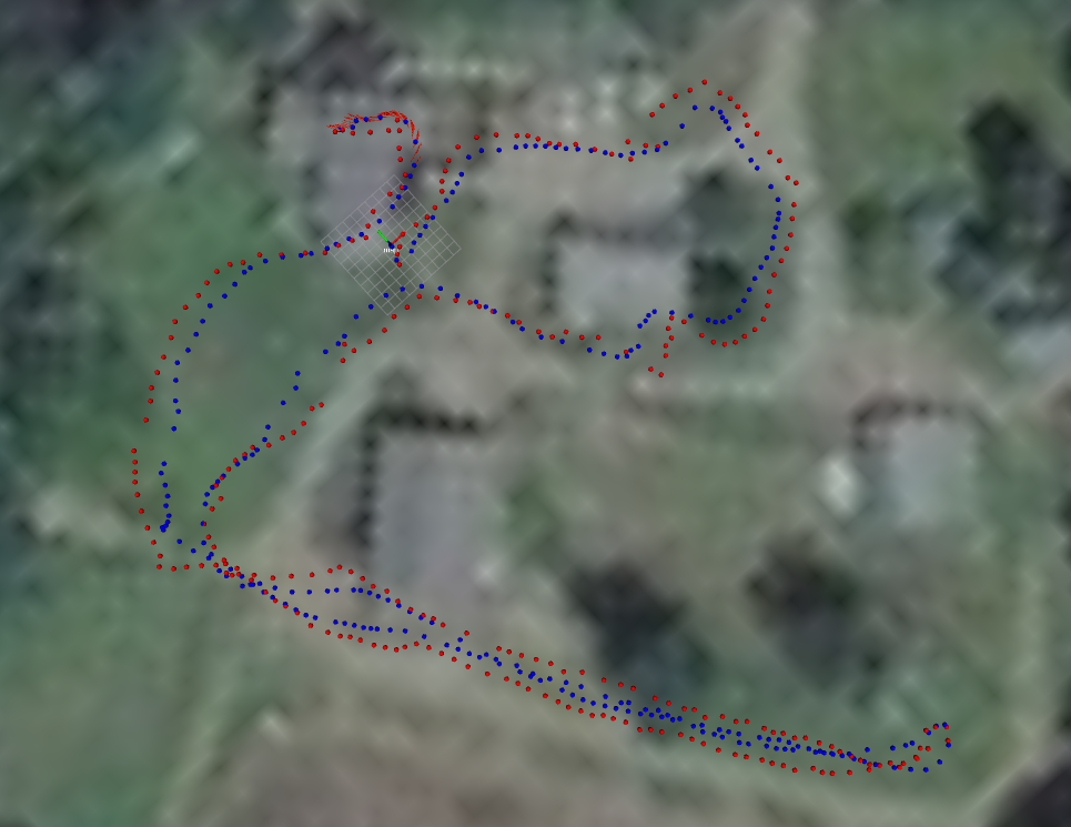
The above image shows localization during a test run. The red dots are the raw GPS data. The blue dots are the output of the EKF. I’m downsampling here to 1 meter spacing between dots. It’s worth noting that the robot actually stayed on the gravel-colored paths, so the raw GPS is pretty far off (especially the track on the left that swings way out into the grass). The datasheet for the MTK3339-based GPS states that the positional accuracy is 2.5 meters (50% CEP), which is quite a bit worse than the Garmin 18x referenced in the robot_localization paper.
At this point, I have decent global localization for how bad the GPS signal is. The next step is going to be replacing the GPS module with one that supports Real Time Kinematics (RTK). The cost of these modules have come down a great deal and so it makes total sense to upgrade to this. There really aren’t any publicly accessible RTK base stations here in New Hampshire, so I’ll also be setting up a base station.
Even while I wait for the new GPS modules to show up, I plan to make some progress on navigation since the localization is still pretty decent within the map frame, and I can temporarily shift the goal poses for testing.