Navigation in ROS2
01 Sep 2020ubr1 robots ros2 With a map having been built and localization working, it was time to get autonomous navigation working on the UBR-1.
Comparing with ROS1
While many of the ROS1 to ROS2 ports basically amount to a find-and-replace of the various ROS interfaces and CMake directives, navigation got a fairly extensive re-architecture from the package that I’ve helped maintain over the past seven years.
A number of the plugin interfaces in ROS1 have been replaced with action interfaces. While the planners themselves are still plugins, they are each loaded into a server node which exposes an action interface to access the planning functions.
One of the biggest changes in ROS2 is the use of behavior trees to structure the recovery behaviors and connect the various action-based interfaces. This allows quite a bit of interesting new functionality, such as using different recovery behaviors for controller failures than are used for planning failures and allowing quite a bit of control over when to plan. There are already dozens of behavior tree nodes and a there is also a new tutorial on writing custom behavior tree nodes.
In ROS1, the navigation stack contains two local “planners”: trajectory_rollout
and dwa (the Dynamic Window Approach). ROS2 fixes this horrid naming
issue and properly calls these “controllers”, but only includes the updated
dwb implementation of the Dynamic Window Approach. As far as
I can remember, I’ve only ever used trajectory rollout as I was never sold on DWA.
I’m still not sold on DWB.
Initial Launch Files
Setting up the navigation to run followed a pretty similar pattern to setting up
SLAM and localization: I copied over the example launch files from the
nav2_bringup package and started modifying things. The real difference
was the magnitude of things to modify.
A note of caution: it is imperative that you use the files from the proper branch.
Some behavior tree modules have been added in the main branch that
do not yet exist in the Foxy release. Similarly some parameters have been renamed or
added in new releases. Some of these will likely get backported, but the simplest
approach is to use the proper launch and configuration files from the start.
My initial setup involved just the base laser scanner. I configured both the local
and global costmaps to use the base laser. It is important to set the robot_radius
for your robot (or the footprint if you aren’t circular). The full configuration can
be found in the ubr1_navigation package, but here is a snippet of
my local costmap configuration:
local_costmap:
   local_costmap:
     ros__parameters:
       global_frame: odom
       robot_base_frame: base_link
       rolling_window: true
       width: 4
       height: 4
       resolution: 0.05
       robot_radius: 0.2413
       plugins: ["voxel_layer", "inflation_layer"]
       inflation_layer:
         plugin: "nav2_costmap_2d::InflationLayer"
         cost_scaling_factor: 3.0
       voxel_layer:
         plugin: "nav2_costmap_2d::VoxelLayer"
         enabled: True
         publish_voxel_map: True
         origin_z: 0.0
         z_resolution: 0.05
         z_voxels: 16
         max_obstacle_height: 2.0
         mark_threshold: 0
         observation_sources: scan
         scan:
           topic: /base_scan
           max_obstacle_height: 2.0
           clearing: True
           marking: True
           data_type: "LaserScan"
A fairly late change to my configuration was to adjust the size of the local costmap. By default, the turtlebot3 configuration uses a 3x3 meter costmap, which is pretty small. Depending on your top speed and the simulation time used for the DWB controller, you will almost certainly need a larger map if your robot is faster than a turtlebot3.
With this minimal configuration, I was able to get the robot rolling around autonomously!
Tilting Head Node
The UBR-1 has a depth camera in the head and, in ROS1, would tilt the camera up and
down to carve out a wider field of view when there was an active navigation goal.
The tilt_head.py script also pointed the head in the direction of the
the local plan. The first step in adding the head camera to the costmaps was porting the
tilt_head.py
script to ROS2.
One complication with a 3d sensor is the desire to use the floor plane for clearing the costmap, but not marking. A common approach for this is to setup two observation sources. The first source is setup to be the marking source and has a minimum obstacle height high enough to ignore most noise. A second source is set to be a clearing source and uses the full cloud. Since clearing sources are applied before marking sources, this works fine and won’t accidentally over clear:
observation_sources: base_scan tilting_cloud tilting_cloud_clearing
base_scan:
  topic: /base_scan
  max_obstacle_height: 2.0
  clearing: True
  marking: True
  data_type: "LaserScan"
tilting_cloud:
  topic: /head_camera/depth_downsample/points
  min_obstacle_height: 0.2
  max_obstacle_height: 2.0
  clearing: False
  marking: True
  data_type: "PointCloud2"
tilting_cloud_clearing:
  topic: /head_camera/depth_downsample/points
  min_obstacle_height: 0.0
  max_obstacle_height: 0.5
  clearing: True
  marking: False
  data_type: "PointCloud2"
In setting this up, I had to set the minimum obstacle height quite high (0.2 meters is almost 8 inches). This is a product of the robot not being entirely well calibrated and the timing accuracy of the sensor causing the points to sometimes rise out of the plane. We’ll improve that below.
You’ll notice I am using a “depth_downsample/points” topic. As inserting full VGA clouds into the costmap would be prohibitively costly, I downsample the depth image to 160x120 and then turn that into a point cloud (a common approach you’ll find on a number of ROS1 robots). This was added to my head_camera.launch.py:
# Decimate cloud to 160x120
ComposableNode(
  package='image_proc',
  plugin='image_proc::CropDecimateNode',
  name='depth_downsample',
  namespace=LaunchConfiguration('namespace'),
  parameters=[{'decimation_x': 4, 'decimation_y': 4}],
  remappings=[('in/image_raw', 'depth_registered/image_rect'),
              ('in/camera_info', 'depth/camera_info'),
              ('out/image_raw', 'depth_downsample/image_raw'),
              ('out/camera_info', 'depth_downsample/camera_info')],
),
# Downsampled XYZ point cloud (mainly for navigation)
ComposableNode(
  package='depth_image_proc',
  plugin='depth_image_proc::PointCloudXyzNode',
  name='points_downsample',
  namespace=LaunchConfiguration('namespace'),
  remappings=[('image_rect', 'depth_downsample/image_raw'),
              ('camera_info', 'depth_downsample/camera_info'),
              ('points', 'depth_downsample/points')],
),
As with the several
other
of the image_proc components I’ve work with, the CropDecimateNode
needed some patches
to actually function.
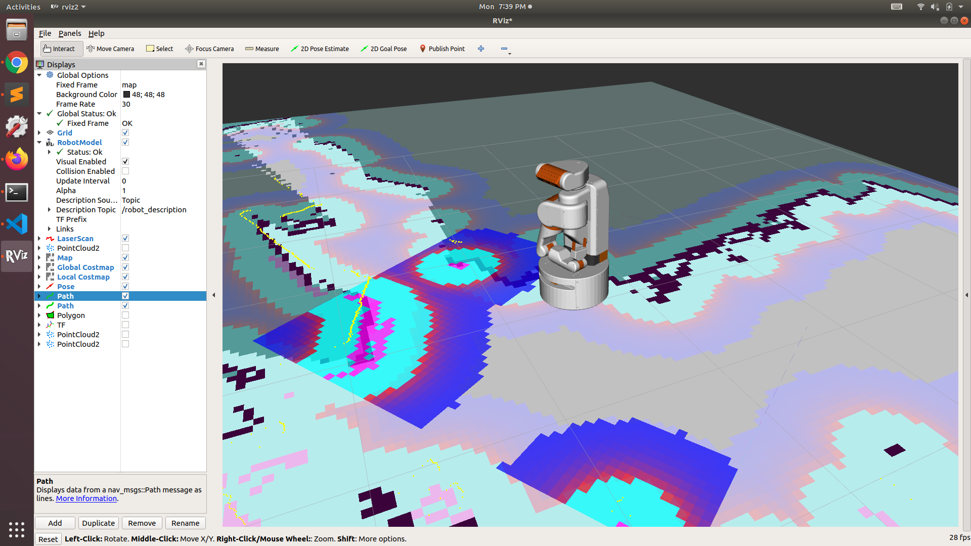
With this in place, things almost worked. But I was getting a bunch of errors about the sensor origin being off the map. This made no sense at first - the robot is clearly on the map - I can see it right in RVIZ! I then started reviewing the parameters:
z_resolution: 0.05
z_voxels: 16
max_obstacle_height: 2.0
At which point I realized that 0.05 * 16 = 0.8 meters. Which is shorter than my robot. So, the sensor was “off the map” - in the Z direction. Pesky 3d.
I updated the voxel configuration so that my map was indeed two meters tall and all my sensor data was now in the costmap.
z_resolution: 0.125
z_voxels: 16
max_obstacle_height: 2.0
Unfortunately, even with my 0.2 meter minimum obstacle height I was still getting stray noisy pixels causing the robot to navigate somewhat poorly at times. In particular, it decided to really come to a halt during a talk and demo to the Homebrew Robotics Club last week.
A Custom Costmap Layer
Setting the minimum obstacle height super high is really not a great idea to begin with. With the Fetch Mobile Manipulator we implemented a custom costmap layer that would find the ground plane using OpenCV and then split the cloud into clearing and marking pixels. This largely avoids the timing and calibration issues, although the marking pixels may be slightly off in their location in the costmap due to those timing and calibration issues. On the Fetch, we were able to get the minimum obstacle height of that moving sensor down to 0.06 meters. In addition, this layer subscribes to the depth image, rather than a 3d point cloud, which allows us to do certain pre-processing less expensively in 2d.
After the HBRC failures, I decided to port the FetchDepthlayer to ROS2.
You can find it in the ubr1_navigation package.
The initial port
was pretty straight forward. The costmap_2d package hasn’t gotten
too many updates, other than a nav2 prefix for the package and
namespaces.
One interesting find was that the sensor_msgs/PointCloud message has been
deprecated and slated for removal after Foxy.
There are a number of places where the PointCloud interface was used a simple way to publish debug
points (the message is simply an array of geometry_msgs/Point32 instead of the
much more complicated PointCloud2 messages which has a variable set of fields
and pretty much requires the use of a modifier and iterator to really fill or read).
I decided to get rid of the deprecation notices and port to PointCloud2 for
the debugging topics -
you can see how much more complicated the code now looks.
Finally, as I started to test the code on the robot, I ran into a few further
issues. Apparently, ROS2 does not just have Lifecyle Nodes, there are also Lifecycle
Publishers. And nav2 uses them. And you need to call on_activate
on them before publishing to them. You can see my final fixes
in this commit.
A final improvement to the node was to remove the somewhat complicated (and I’m
guessing quite slow) code that found outliers. Previously this was done by finding
points in which less than seven neighbors were within 0.1m away, now I use
cv::medianBlur on the depth image.
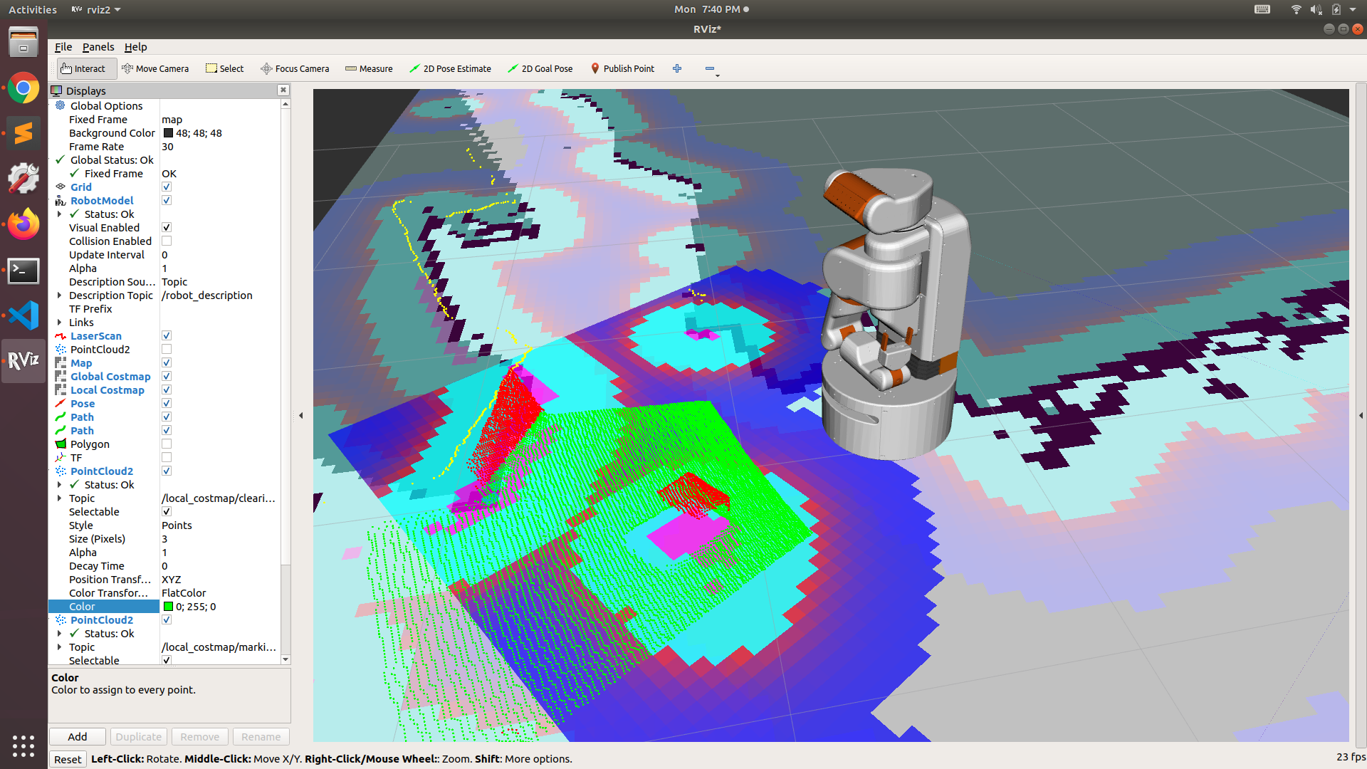
The image below shows the costmap filled in for a box that is shorter than my laser scanner, but detected by camera. The red and green points are the marking and clearing debug topics from the depth layer:
Test on Robots!
One of the more interesting moments occurred after I updated my sources for navigation2. Suddenly, the robot was unable to complete goals - it would get to the goal and then rotate back and forth and eventually give up. I ended up tracking down that a major bug had been introduced during a refactor which meant that when comparing the goal to the current pose they were not in the same frame! The goal would be in the map frame, but the local controller was taking robot pose in the odom frame. The only time a goal could succeed was if the origins of the map and odom frame were aligned (which, coincidentally, probably happens a lot in simulation). My fix was pretty simple and the bug never made it into released Debians in Foxy, but it did exist for almost a month on the main branch.
Tuning the Local Controller
As a side effect of the goal bug, I ended up spending quite a bit of time tuning the local controller (thinking that it was responsible for the issues I was seeing). Both the overall architecture and the parameters involved are somewhat different from ROS1.
Let’s first mention that the controller server implements a high pass filter on the odometry
topic to which it subscribes. This filter has three parameters:
min_x_velocity_threshold, min_y_velocity_threshold, and
min_yaw_velocity_threshold. While debugging, I ended
up updating the descriptions of these parameters in the
navigation documentation
because I was at first trying to use them as the minimum velocities to control, since
the original description was simply “Minimum velocity to use”.
The controller server still loads the controller as a plugin, but also has separate
plugins for the goal checker and progress checker. The SimpleProgressChecker
is pretty straight forward, it has two parameters and requires that the robot move at
least X distance in T time (default 0.5 meters in 10 seconds).
The SimpleGoalChecker implements the goal check that previously was part
of the controller itself. As in ROS1, it has three parameters:
xy_goal_toleranceis how close the robot needs to get to the goal. By default, the xy tolerance is set quite course. I tightened that tolerance up on the UBR-1.statefulis similar to “latching” in ROS1 stack. Once the robot has met the xy_goal_tolerance, it will stop moving and simply rotate in place.yaw_goal_toleranceis how close to the heading is required to succeed.
One of the enhancements of DWB over the DWA implementation is that it splits each of the
individual elements of trajectory scoring into a separate plugin. This makes it easier
to enable or disable individual elements of the scoring, or add custom ones. For instance,
you could entirely remove the PathAlign element if it is causing issues and
you don’t care if your robot actually follows the path.
There are two major hurdles in tuning the DWB controller: balancing the path and goal scores, and balancing smooth operation versus actually getting to the end of the trajectory (as opposed to just stuttering towards the goal slowly). I think the first one is well tuned on the UBR-1, but I’ve not yet fixed the stuttering to the goal well enough to be happy with the controller. You can find that several others have also struggled to get the performance they were seeking.
Next Steps
Now that I’ve got navigation mostly working, the next big hurdle is manipulation. I have MoveIt2 compiled, but am still working through the requisite launch files and other updates to make things work for my robot. And then onto the real goal of every roboticist: having my robot fetch a beer.