Mapping and Localization in ROS2
19 Aug 2020ubr1 robots ros2 Now that the drivers are pretty much operational for the UBR-1 robot under ROS2, I’m starting to work on the higher level applications. The first step was building a map and setting up localization against that map.
SLAM
In ROS1 there were several different Simultaneous Localization and Mapping (SLAM)
packages that could be used to build a map: gmapping, karto, cartographer, and
slam_toolbox. In ROS2, there was an early port of cartographer, but it is really not
maintained. The other package that has been ported to ROS2 is slam_toolbox,
which is basically slam_karto on steroids - the core scan matcher is
the same, but everything else has been rewritten and upgraded.
Installation of slam_toolbox is super easy:
sudo apt-get install ros-foxy-slam-toolbox
I then created a launch file, which is an updated version of the online_sync_launch.py
found within slam_toolbox:
from launch import LaunchDescription
from launch.actions import DeclareLaunchArgument
from launch.substitutions import LaunchConfiguration
from launch_ros.actions import Node
from ament_index_python.packages import get_package_share_directory


def generate_launch_description():
    use_sim_time = LaunchConfiguration('use_sim_time')

    declare_use_sim_time_argument = DeclareLaunchArgument(
        'use_sim_time',
        default_value='false',
        description='Use simulation/Gazebo clock')

    start_sync_slam_toolbox_node = Node(
        parameters=[
          get_package_share_directory("ubr1_navigation") + '/config/mapper_params_online_sync.yaml',
          {'use_sim_time': use_sim_time}
        ],
        package='slam_toolbox',
        node_executable='sync_slam_toolbox_node',
        name='slam_toolbox',
        output='screen')

    ld = LaunchDescription()

    ld.add_action(declare_use_sim_time_argument)
    ld.add_action(start_sync_slam_toolbox_node)

    return ld
My updates were basically just to use my own config.yaml file. In that YAML file I had to update the frame ids (I don’t use a base_footprint, and my robot has a base_scan topic rather than scan). There are dozens of parameters to the Karto scan matcher and you can see the entire file on GitHub but the basic changes I had to make were:
slam_toolbox:
  ros__parameters:

    # ROS Parameters
    odom_frame: odom
    map_frame: map
    base_frame: base_link
    scan_topic: /base_scan
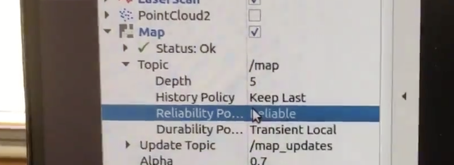
Now we can run the launch file and drive the robot around to build a map. We can also view the map in RVIZ. To get the map to come through, you will likely have to expand the options under the topic name and change the durability to transient local. Even though the documentation on ROS2 QoS says that volatile subscriber is compatible with a transient local publisher, I’ve found it doesn’t always seem to work right:
Now that we’ve built a map, it is time to save the map. The command is quite similar to ROS1, except you must pass the base name of the map (so here, I’m passing map, which means it will save map.yaml and map.pgm in the local directory):
ros2 run nav2_map_server map_saver_cli -f map
Next we can create a launch file to display the map - I used the example in nav2_bringup as my starting place and changed which package the map was stored in. You can find my launch file in the ubr1_navigation package. I started my localization launch file and opened RVIZ to find:
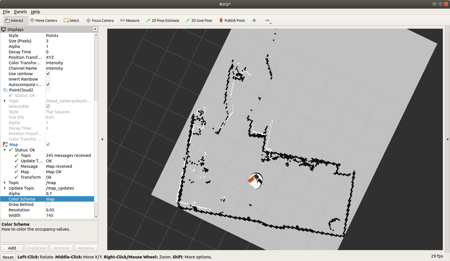
It turned out I had to adjust the free_thresh threshold in the
map.yaml down to 0.196 (the same value in ROS1) for the map to look correct:
There are numerous parameters in slam_toolbox and many more features
than I could possibly cover here. For a good introduction, check out
ROSCon 2019 Talk by Steve Macenski.
Localization
While there are a variety of mapping options in ROS1 and some in ROS2, for localization it really is just Adaptive Monte Carlo Localization (AMCL). There is some ongoing work towards more modern localization solutions in ROS2, but it would seem to be a long way off.
The launch file we copied over for running the map_server also included AMCL in it (hence the name localization.launch.py).
For the most part, there are only a few parameters to tune in AMCL to generally get decent results:
amcl:
  ros__parameters:
    alpha1: 0.25
    alpha2: 0.2
    alpha3: 0.15
    alpha4: 0.2
    base_frame_id: "base_link"
    global_frame_id: "map"
    laser_model_type: "likelihood_field"
    max_beams: 60
    max_particles: 2000
    min_particles: 500
    odom_frame_id: "odom"
    robot_model_type: "differential"
    tf_broadcast: true
    z_hit: 0.6
    z_max: 0.05
    z_rand: 0.3
    z_short: 0.05
Before trying to tune AMCL, you really need to make sure your TF and odometry are setup correctly, there are some points in the Navigation Tuning Guide, which was written for ROS1, but is generally very much true in ROS2.
The most important parameters are setting the alphaX parameters to model your odometry noise. By default all of them are set to 0.2, but they should be adjusted based on the quality of your odometry:
- alpha1 - noise in rotation from rotational motion
- alpha2 - noise in rotation from translational motion
- alpha3 - noise in translation from translational motion
- alpha4 - noise in translation from rotational motion
These are somewhat intuitive to understand. For most robots, if they drive forward in a straight line, the odometry is very accurate - thus alpha3 is often the lowest value parameter. When the robot turns in place, it probably has more noise (unless you have a fantastically tuned gyro being merged with the wheel odometry) - so alpha1 often gets bumped up. My alpha1 is currently set high since I have not yet integrated the IMU on the UBR-1 into the ROS2 odometry.
When the alpha parameters are set too low, the odometry ends up driving the distribution of particles in the cloud more than the scan matcher. If your odometry is inaccurate, the robot will slowly get delocalized because the particle distribution lacks particles located at the true pose of the robot.
If the alpha parameters are set too high, the particle distribution spreads out and can induce noise in your pose estimate (and cause delocalization).
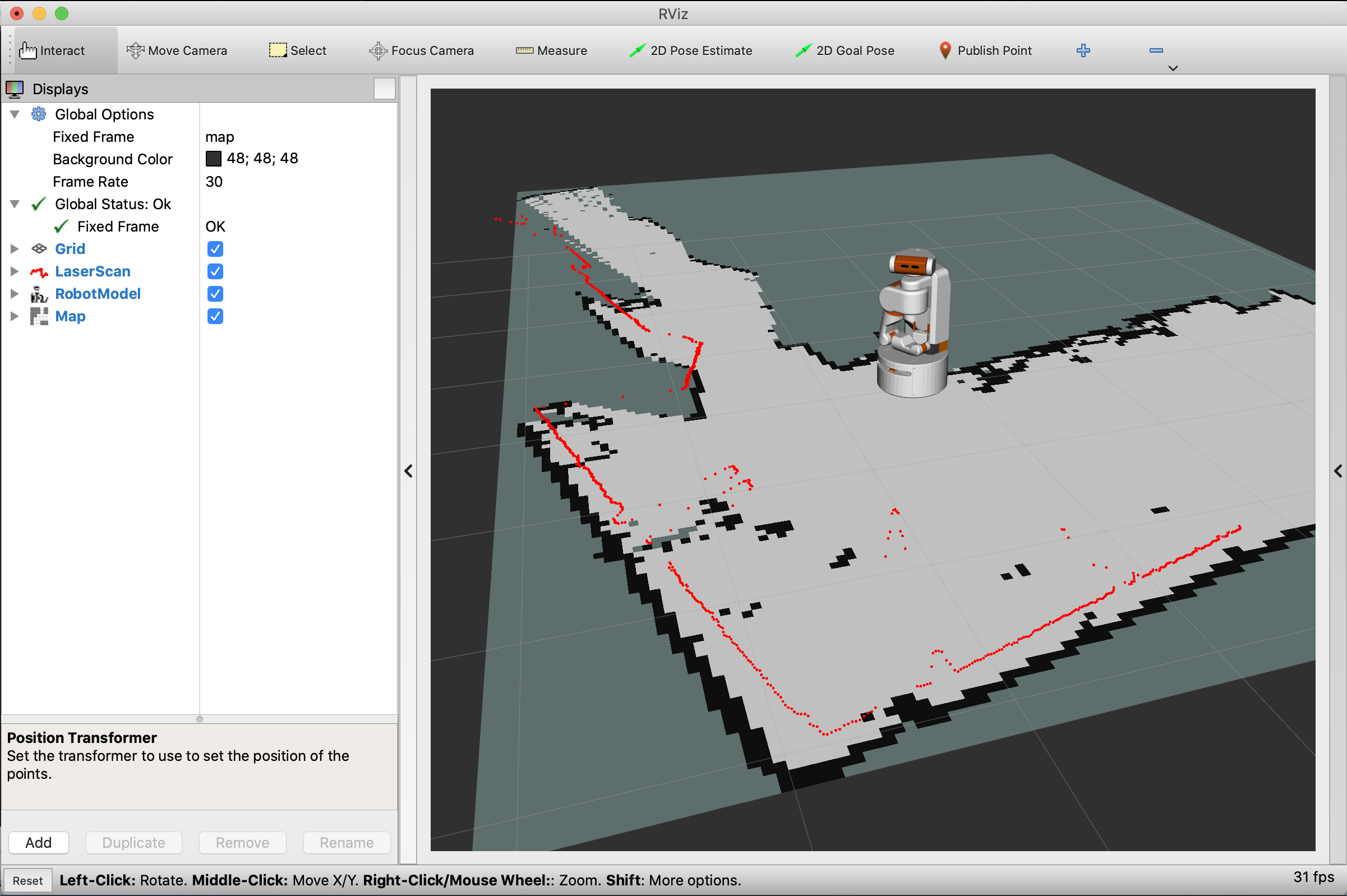
One of the best ways to test these parameters is in RVIZ. Add your laser scan to the display, and set the fixed frame of RVIZ to your map frame. Then turn the “Decay Time” of the laser way up (20-100 seconds). If your parameters are correct, the laser scans will all line up very well. If the parameters are crap, the walls raycast by the laser scanner will be very “thick” or unaligned.
To tune these parameters, I will often drop all of them lower than the default, usually something like 0.05 to 0.1 for each parameter.
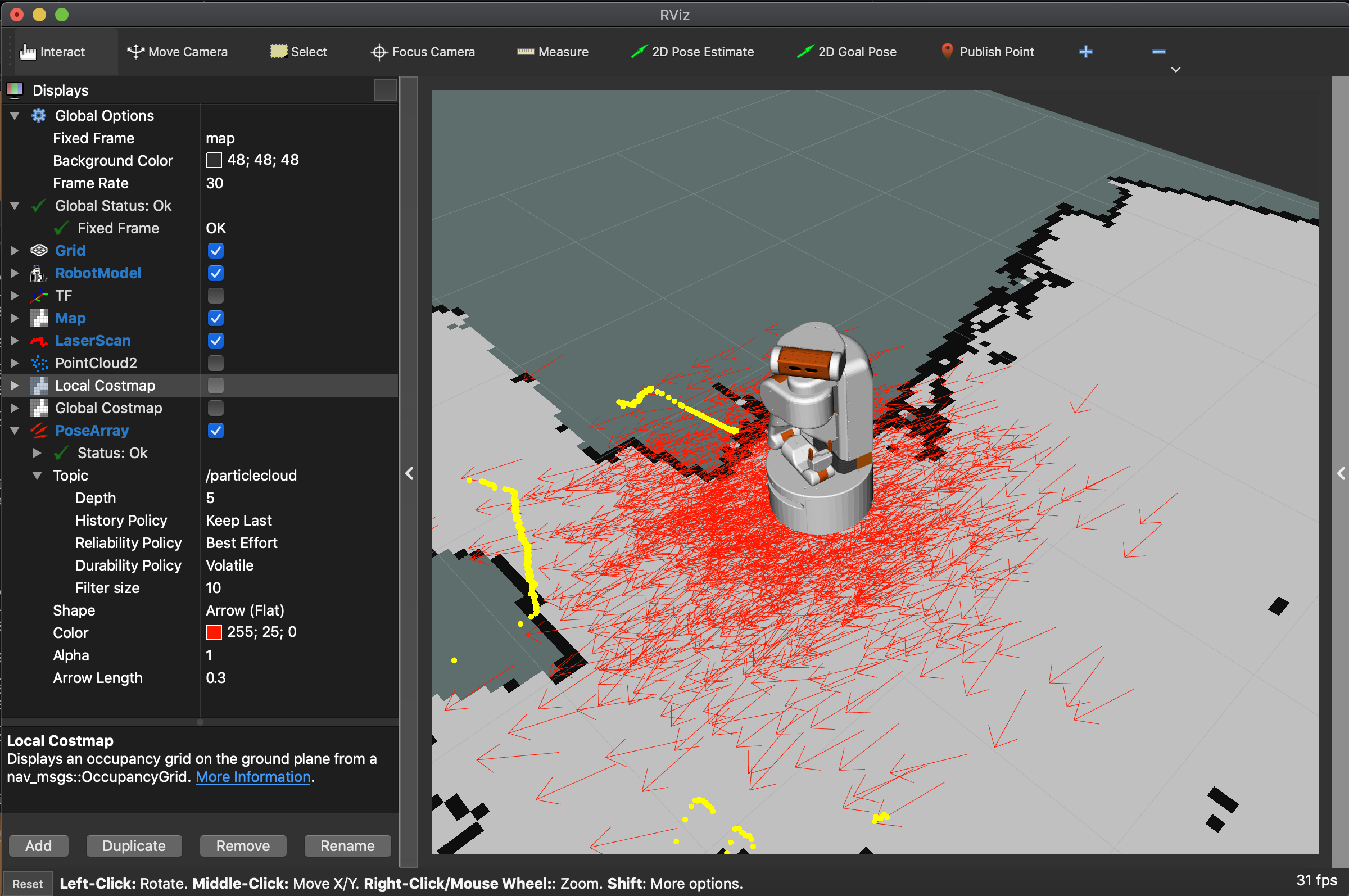
A final check is to display the /particlecloud published by AMCL and
make sure it isn’t diverging too much - if it is, you might have to reduce your
alpha parameters. To see the particle cloud, you’ll have to switch the QoS to
best effort. The image below shows what the cloud looks like when the robot is
first localized, it should be a lot less spread out during normal operation: