There was a shortage of entries in the
tablebot competition
shortly before the registration window closed for RoboGames 2023. To make sure the
contest would be held, I entered a robot. Then I had to build one.
What’s A Tablebot?
A tablebot lives on the table. There are three “phases” to the competition:
Phase I: Build a robot that goes from one end of a table to the other and back.
Phase II: Have the robot push a block off the ledge of the table.
Phase III: Have the robot push the block into a shoebox mounted at the end of the table.
There is also an unofficial Phase IV - which is to fall off the table and survive.
I did not attempt this phase.
The majority of tablebots are quite simple - a couple of sonar or IR sensors and they
kind of wander around the tabletop in hopes of completing the different phases. My
tablebot is decidedly different - and it paid off as the robot won the gold medal at
RoboGames 2023.
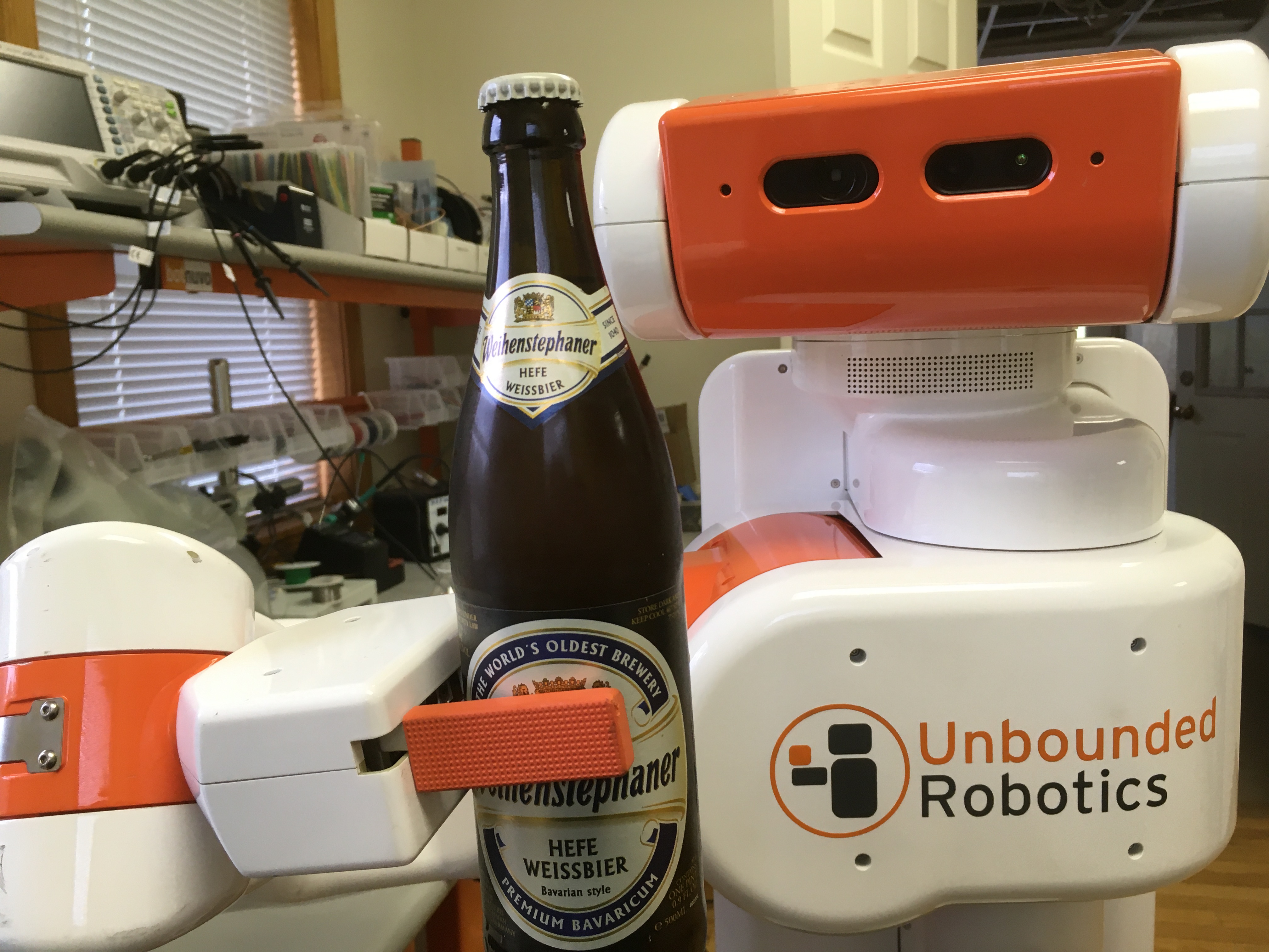
Robot Build
The entire robot is built of 3d printed parts and random things I had on hand.
I’ve had one of those $99 LD-06 lidars sitting around for a while, and decided this was
a great project to use it on. I used a Dynamixel AX-12 servo to tilt the laser so I can
find the table, the cube, or the goal.
All of the code runs on an STM32, on my custom Etherbotix board which was designed
for my Maxwell robot
a number of years ago. The robot uses
differential drive with some 30:1 12V gear motors, which were purchased from
Lynxmotion in 2008 and used in various fire fighting robots over the years.
A set of small digital Sharp IR sensors are used as cliff sensors. These can
be moved up or down to calibrate for different table surfaces using a pair of
adjustment screws. While the sensors are very accurate and stop the robot,
they don’t see far enough ahead when going at full speed, and so I also
use the laser to detect when the table edge is approaching.
Phase 1 Software
Phase 1 is pretty straight forward - and mostly based on dead reckoning odometry:
The laser is angled downwards looking for the table. This is done by projecting to
the scan to 3d points, and filtering out anything not in front of the robot at
roughly table height. When the table disappears (number of points drops too low),
we reduce our maximum speed to something that is safe for the cliff sensors to
detect.
While the laser sensors look for the end of the table, the robot drives forward,
and a simple feedback loop keeps the robot centered on the table using odometry.
When the cliff sensors eventually trigger, the robot stops, backs up 15 centimeters,
and then turns 180 degrees - all using dead reckoning odometry.
The maximum speed is then reset and we take off to the other end of the table with
the same behavior.
Phase 2 Software
The movements of Phase 2 are basically the same as Phase 1 - we drive forward,
staying centered with odometry. The speed is a bit lower than Phase 1 because the
laser is also looking for the block:
The laser scan is projected to 3d, and we filter out any points that are part
of the table based on height. These remaining points are then clustered and
the clusters are analyzed for size.
If a cluster is a good candidate for the block, the robot turn towards the block
(using, you guessed it, dead reckoning from odometry).
The robot then drives towards the block using a simple control loop to keep
the heading.
Once the block is arrived at, the robot drives straight until a cliff sensor
trips.
At that point, the robot stops the wheel on the side of the tripped cliff sensor
and drives the other wheel very slowly forward so that we align the front of
the robot with the edge of the table - ensuring the block has been pushed off
the table.
Phase 3 Software
The final phase is the most complex, but not by much. As with the earlier phases,
the robot moves down the table finding the block:
Unlike in Phase 2, the robot actually approaches a pose just behind the block.
Once that pose has been reached, the robot tilts the laser back to level and
finds the goal.
The robot then turns towards the goal in the same way it first turned towards
the block.
The robot then approaches the goal using the same simple control loop, and in
the process ends up pushing the block to the goal.
All of the software for my Tablebot is availble on
GitHub.
Robogames Video
Jim Dinunzio, a member of the Homebrew Robotics Club, took a video during the
actual competition at Robogames so you can actually see the winning set of runs:
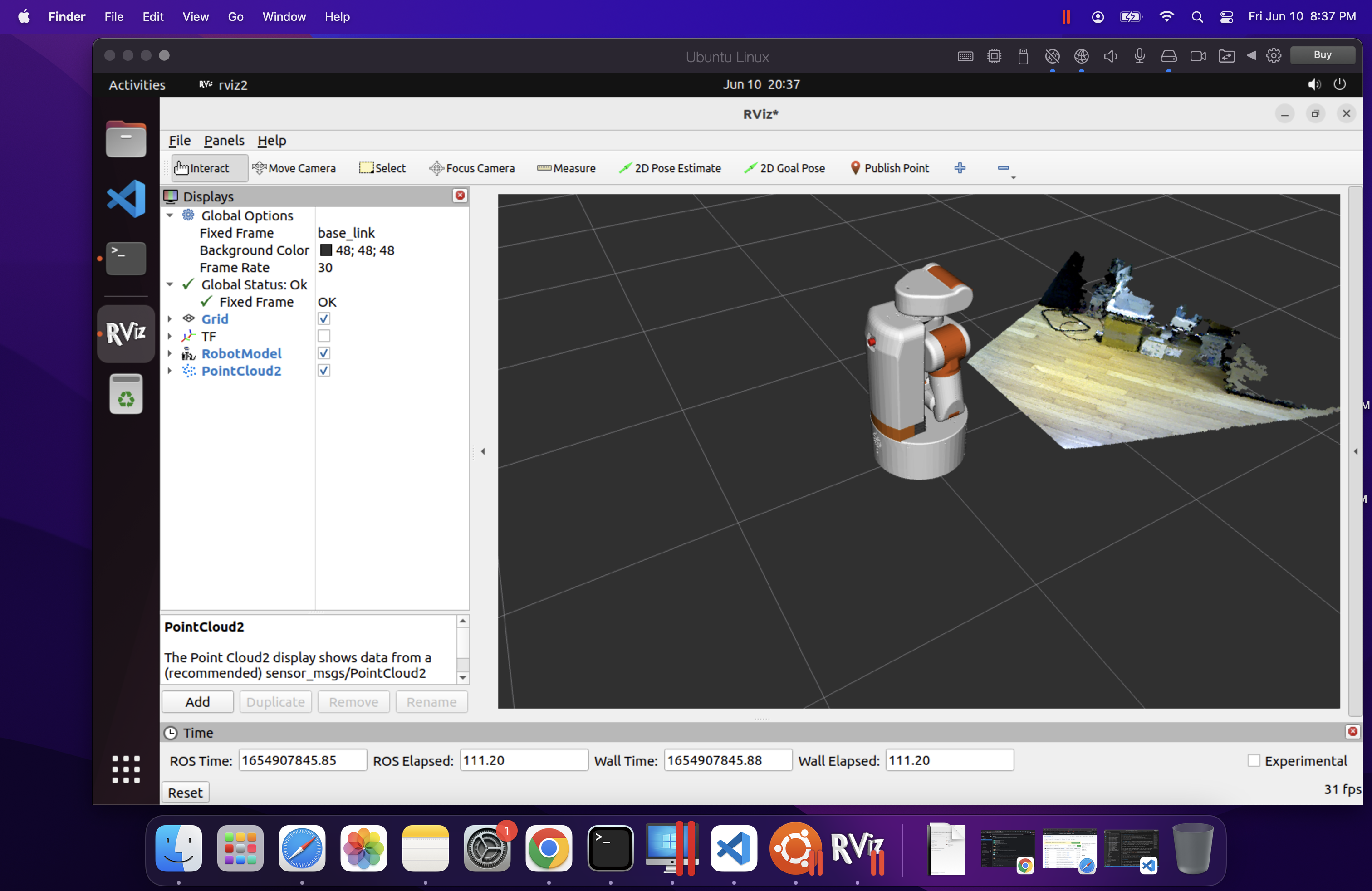
Visualization
To make development easier, I also wrote a Python GUI that renders the table,
the robot odometry trail, the laser data, and detected goals and cubes.
Fun with Math
Along the way I actually ran into a bug in the ARM CMSIS DSP library. I used the
arm_sin_cos_f32() function to compute my odometry:
This function takes the angle (in degrees!) and returns the sine and cosine of the
angle using a lookup table and some interesting interpolation. With the visualization
of the robot path, I noticed the robot odometry would occasionally jump to the
side and backwards - which made no sense.
Further investigation showed that for very small negative angles,
arm_sin_cos_f32 returned huge values. I dug deeper into the code and
found that there are several different versions out there:
The version from my older STM32 library, had this particular issue at very
small negative numbers. The same bug was still present in the official CMSIS-DSP
on the arm account.
The version in the current STM32 library had a fix for this spot - but that fix
then broke the function for an entire quadrant!
The issue turned out to be quite simple:
The code uses a 512 element lookup table.
For a given angle, it has to interpolate between the previous and next
entry in the table.
If your angle fell between the 511th entry and the next (which would be
the 0th entry due to wrap around) then you used a random value in the next
memory slot to interpolate between (and to compute the interpolation).
At one point, this resulted in sin(-1/512) returning outrageous values of
like 30.
With that bug fixed, odometry worked flawlessly afterwards. As it turned out,
I had this same function/bug existing in some brushless motor control code at
work.
Robogames Wrap Up
It is awesome that RoboGames is back! This little robot won’t be making another
appearance, but I am starting to work on a RoboMagellan robot for next year.
It has been a while since I’ve posted to the blog, but lately I’ve actually been working
on the UBR-1 again after a somewhat long hiatus. In case you missed the earlier posts in
this series:
The latest ROS2 release came out just a few weeks ago. ROS2 Humble targets Ubuntu 22.04
and is also a long term support (LTS) release, meaning that both the underlying Ubuntu
operating system and the ROS2 release get a full 5 years of support.
Since installing operating systems on robots is often a pain, I only use the LTS releases
and so I had to migrate from the previous LTS, ROS2 Foxy (on Ubuntu 20.04). Overall, there
aren’t many changes to the low-level ROS2 APIs as things are getting more stable and mature.
For some higher level packages, such as MoveIt2 and Navigation2, the story is a bit different.
Visualization
One of the nice things about the ROS2 Foxy release was that it targeted the same operating
system as the final ROS1 release, Noetic. This allowed users to have both ROS1 and ROS2
installed side-by-side. If you’re still developing in ROS1, that means you probably don’t
want to upgrade all your computers quite yet. While my robot now runs Ubuntu 22.04, my
desktop is still running 18.04.
Therefore, I had to find a way to visualize ROS2 data on a computer that did not have the
latest ROS2 installed. Initially I tried the Foxglove Studio, but didn’t have any luck
with things actually connecting using the native ROS2 interface (the rosbridge-based
interface did work). Foxglove is certainly interesting, but so far it’s not really
an RVIZ replacement - they appear to be more focused on offline data visualization.
I then moved onto running rviz2 inside a docker environment - which works
well when using the rocker tool:
If you are using an NVIDIA card, you’ll need to add --nvidia along with
--x11.
In order to properly visualize and interact with my UBR-1 robot, I needed to add the
ubr1_description package to my workspace in order to get the meshes and
also my rviz configurations. To accomplish this, I needed to create my own docker
image. I largely based it off the underlying ROS docker images:
The image derives from humble-desktop and then adds the build tools and clones
my repository. I then ignore the majority of packages, install dependencies and
then build the workspace. The ros_entrypoint.sh script handles
sourcing the workspace configuration.
The full source of these docker configs is in the
docker folder
of my ubr_reloadedrepository. NOTE: The updated code in the
repository also adds a late-breaking change to use CycloneDDS as I’ve had
numerous connectivity issues with FastDDS that I have not been able to debug.
Visualization on MacOSX
I also frequently want to be able to interact with my robot from my Macbook. While I previously
installed ROS2 Foxy on my Intel-based Macbook,
the situation is quite changed now with MacOSX being downgraded to Tier 3 support and the new
Apple M1 silicon (and Apple’s various other locking mechanisms) making it harder and harder
to setup ROS2 directly on the Macbook.
As with the Linux desktop, I tried out Foxglove - however it is a bit limited on Mac. The
MacOSX environment does not allow opening the required ports, so the direct ROS2 topic
streaming does not work and you have to use rosbridge. I found I was able to visualize
certain topics, but that switching between topics frequently broke.
At this point, I was about to give up, until I noticed that Ubuntu 22.04 arm64 is a Tier 1
platform for ROS2 Humble. I proceeded to install the arm64 version of Ubuntu inside Parallels
(Note: I was cheap and initially tried to use the VMWare technology preview, but was unable
to get the installer to even boot). There are a few tricks here as there is no arm64 desktop
installer, so you have to install the server edition and then upgrade it to a desktop. There
is a detailed description of this workflow on askubuntu.com.
Installing ros-humble-desktop from arm64 Debians was perfectly easy.
rviz2 runs relatively quick inside the Parallels VM, but overall it was not
quite as quick or stable as using rocker on Ubuntu. However, it is really nice
to be able to do some ROS2 development when traveling with only my Macbook.
Migration Notes
Note: each of the links in this section is to a commit or PR that implements the discussed
changes.
In the core ROS API, there are only a handful of changes - and most of them are actually
simply fixing potential bugs. The logging macros have been updated for security purposes
and require c-strings like the old ROS1 macros did. Additionally the macros are now
better at detecting invalid substitution strings. Ament has also gotten better at
detecting missing dependencies. The updates I made to
robot_controllers
show just how many bugs were caught by this more strict checking.
image_pipeline has had some minor updates since Foxy, mainly to improve
consistency between plugins and so I needed to
update some topic remappings.
Navigation has the most updates. amcl model type names have been
changed
since the models are now plugins. The API of costmap layers has changed significantly,
and so a number of
updates were required
just to get the system started. I then made a more detailed pass through the
documentation and
found a few more issues and improvements with my config,
especially around the behavior tree configuration.
I also decided to do a proper port of
graceful_controller to ROS2,
starting from the latest ROS1 code since a number of improvements have happened in the
past year since I had originally ported to ROS2.
Next Steps
There are still a number of new features to explore with Navigation2, but my immediate
focus is going to shift towards getting MoveIt2 setup on the robot, since I can’t easily
swap between ROS1 and ROS2 anymore after upgrading the operating system.
This year has been quite different than I think most people would have expected. I haven’t
traveled since February, which makes this year the least I’ve traveled in probably a decade.
This allowed me to make some progress on a number of projects, including restarting this
blog.
The UBR-1
Probably the most visible project for the year was buying, restoring, and upgrading to ROS2
a UBR-1 robot. There are quite a few posts you can find under the
ubr1 tag.
In 2021, I’m planning to finally make some progress on running MoveIt2 on the UBR-1.
Botfarm Rev. A
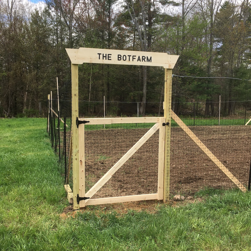
We refer to my farm in New Hampshire as “The Botfarm”, since I mainly grow robots here.
Since I wasn’t going to be traveling this year, it seemed like a great time to actually
start a garden as well.
We fenced off about 2500 square feet for this first garden, although we only ended up planting
about half that space. The fence is seven foot tall plastic mesh, which seems to have worked
pretty well since no deer got in (and they are everywhere here). The
fancy sign over the gate pretty much constitutes my only woodworking project of the year:
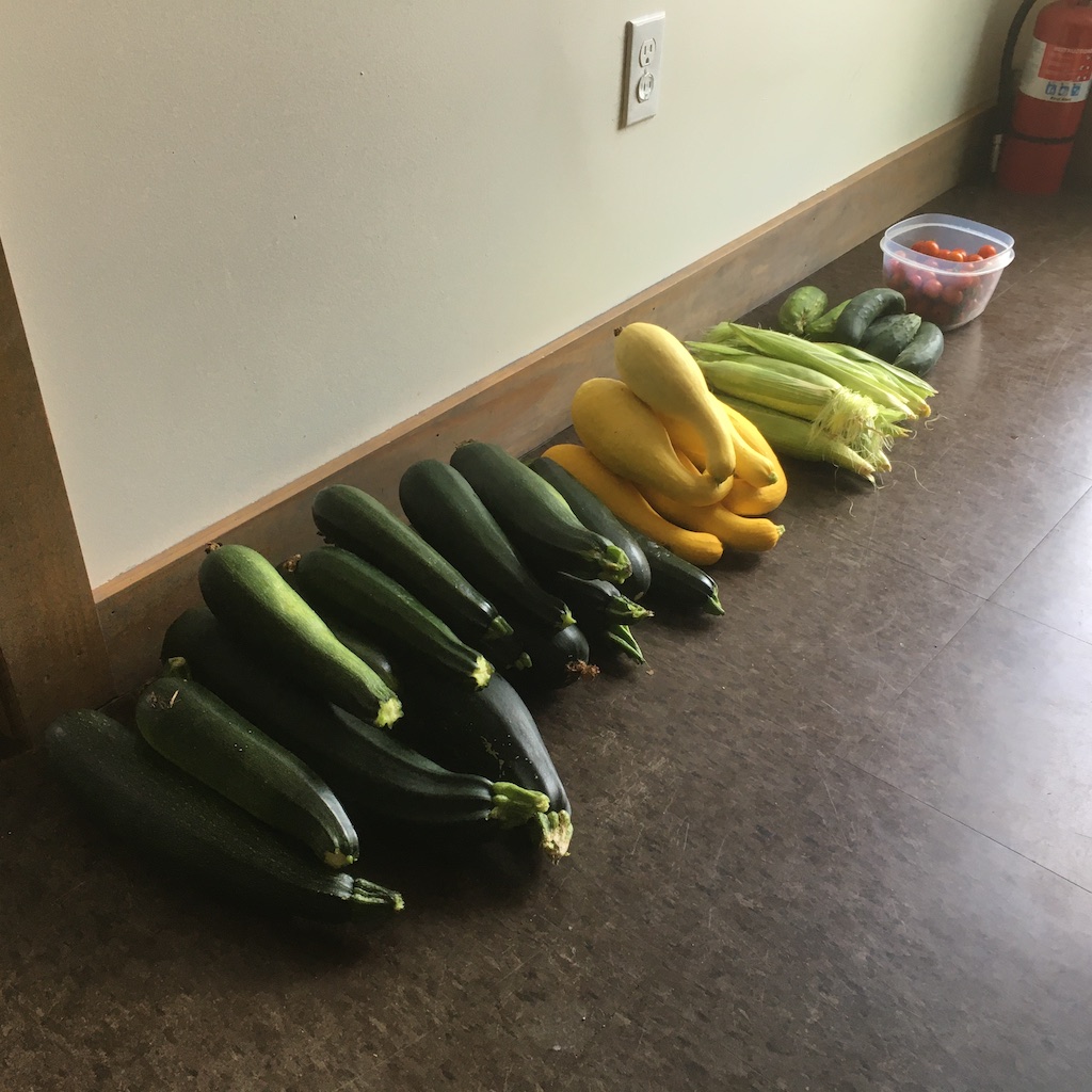
As it turned out, getting seeds for some things was really quite a challenge for the last minute
garden project. In the end, we ended up growing:
Zucchini - 117.25 kg total from a single 50 foot row of plants. Direct seeded.
Squash - 29.7 kg from a half row. Direct seeded.
Cucumbers - 12.8 kg. We planted several store bought plants since I didn’t get the seeds into
ground until quite late. The upside of the “late” plants was that by then I knew they had to
be trellised and so those plants really grew great.
Potatoes - 20 kg harvested from 5 kg planted. Not a great yield - the soil ended up really packing
down hard around the plants after hilling.
Tomatoes - 4 kg of Sweet 100, and 7.7 kg of Beefsteak from two plants of each kind.
Broccoli - was planted way too late, didn’t really start to do anything until the fall. We got
several heads of broccoli.
Pumpkins - 50 kg of pumpkins from 3 plants.
Corn - about a dozen ears. This was another poor yield, the corn was basically planted in the
worst of the soil.
Onions - a bunch of tiny ones - I completely misunderstood how to plant them and put them
way too close together…
Brewing
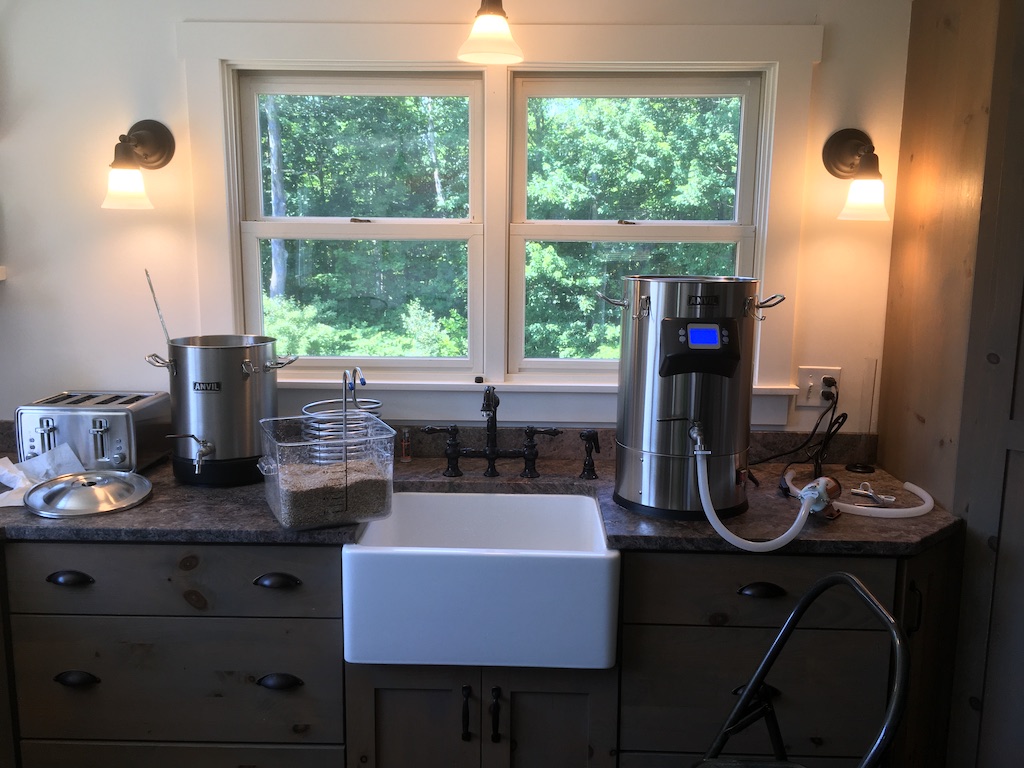
In July, I also started home brewing - something I’ve wanted to do for a while. Of course, I can’t just throw
some things in a kettle on the stove, I had go all process controlled and data driven.
The first component of my setup is an Anvil Foundry electric kettle. This is an all-in-one that
is used as the mash tun and the boil kettle. So far, I’ve gotten lower than expected efficiency from the unit,
but over several batches I’ve been making improvements. At the very end of the year, I picked up a grain mill
(on a great discount) which I’m hoping will further improve efficiency.
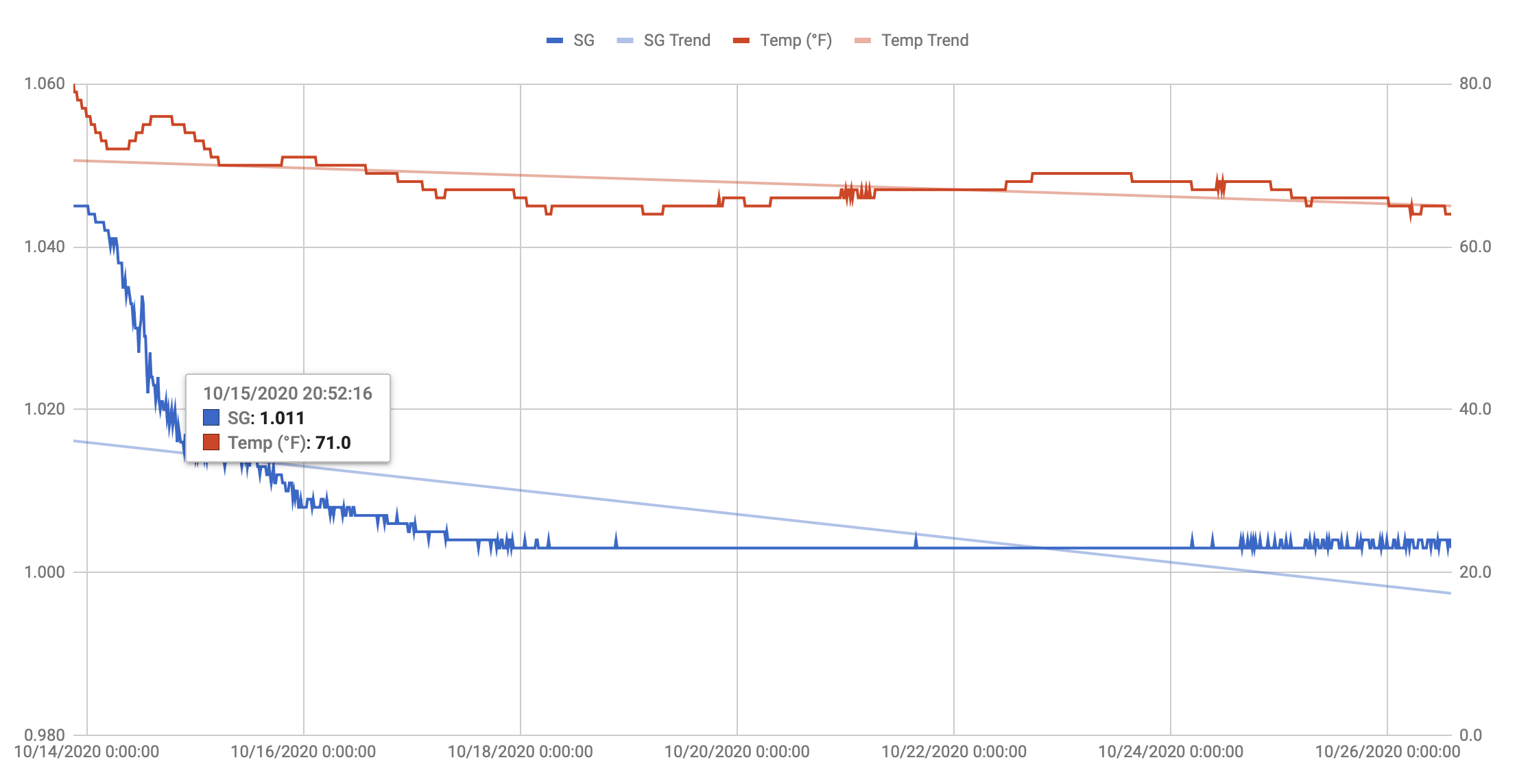
Once the wort is made, I’ve got a Tilt Hydrometer to monitor the fermentation process.
This is an interesting little bluetooth device that wirelessly relays the temperature and specific gravity of the
beer it is floating in. While the absolute value is not entirely accurate, the trend-line is super useful to see when
the fermentation is done (or stuck). The data is recorded every 15 minutes and makes great plots - you can even get
an idea of how active the fermentation is by how noisy the data is at a given point in time:
I didn’t end up brewing much in the summer heat. I did a few batches of Hefeweizens, all of which could be
fermented in the cellar. I’ve been slowly increasing the temperature I want to ferment those at (as well as for
some Belgian styles), which is incompatible with the winter temperatures here in New Hampshire. This fall I
added an electric heat band and a temperature controller so I can keep the beer at the right temperature
during fermentation.
I’m currently working on 3D-printing an orbital shaker to propagate yeast starters - I’ll post on that next year
when it is done.
This fall I also did Virtual Beer School with Natalya Watson and then passed the
Cicerone Beer Server exam. I’m hoping to
complete the next level, Certified Cicerone, next year.
The Shop
While this blog is called “Robot & Chisel”, I did not end up doing any woodworking this year.
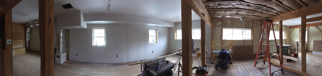
I did make some progress on the shop. One of the selling features of the BotFarm was a big barn on the property
that I have been slowly turning into a shop. There is now heat and insulation in the building and we are
making steady progress on finishing out the space. I’m hoping to have all the woodworking tools moved
in by summer next year.
Next Year
After this year, I’m not even going to try to make predictions of what I’ll work on next year. But I do hope to do some
more ROS2 stuff on the UBR-1 and brew more beers (especially some Saisons and some “fake barrel aged” stuff).